|
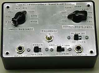
A Zero Loss, Unilateral 'Ideal' Audio Transformer Simulator, plus... This device makes is very easy to determine the optimum audio transformer source and load resistances for any crystal set diode/headphone combination. No test equipment necessary By Ben H. Tongue Quick Summary: This device works as an audio transformer when connected between the output of a diode detector and headphones, but with several differences. (1) No insertion power loss. (2) Input and output resistances can be independently varied over a wide range by selector switches. This provides for the simulation of a wide range of "transformer turns ratios". The main purpose of this device is to enable oneself, by twisting two dials, to find out the optimum audio impedance transformation needed in a 'real world transformer', while experimentally trying different diodes or headphones in a crystal radio set. The effect the transformer has on selectivity and volume may be evaluated. Another purpose is to enable one to check how closely the performance of one's audio transformer conforms to that of an ideal one, both having the same input and output impedances. It also has a switchable 20 dB amplifier to enable better reading of very weak signals. The first version of this device, shown in Figs. 1, 2 and 3 is designed
for driving typical sound-powered balanced-armature, magnetic diaphragm
or piezo electric earphones. The schematic for Version B, shown
in Fig.4 is designed for feeding a wider range of loads, down to an
impedance of 8 ohms. This unit can match the impedance of the
earphones mentioned above as well as that of typical dynamic earphones. 1. What's it good for? Consider a crystal radio set that uses an audio transformer to drive headphones. One can determine what its performance would be if the transformer had no loss and provided an optimum impedance match between the output resistance of the diode detector and the headphone load. One can determine if the optimum diode load resistance changes as a function of signal level by adjusting SW3 for the loudest volume on a weak signal and then readjusting it for a strong one.
3. A Short tutorial on some aspects of audio transformer utilization in crystal sets. One of the issues one encounters when designing a high performance crystal radio set is determining the optimum parameters for the detector-to-headphone audio coupling transformer. Its impedance transformation ratio is the main factor to be considered, though the inherent loss and reactance parameters are also important. Another factor is the primary and secondary impedance levels for which the transformer was designed, compared with the levels to be used in a crystal radio set application. Consider the performance of two transformers having the same transformation ratio, but originally designed to operate at different impedance levels. They will not perform the same. To illustrate this point we will consider a transformer designed to transform a 10,000 Ohm source to a 90,000 Ohm load. This could be an AES PT-156, Stancor A-53C or similar transformer originally designed to couple the output of a first (tube) audio stage to push-pull grids. If the designer did a good job, this transformer will have the lowest possible loss consistent with its specified frequency range, power handling capability and cost goals. If it were to be driven from a 40,000 Ohm source and loaded with a 360,000 Ohm load (still a 1:9 impedance ratio), its center-band power insertion loss will be increased and the low frequency end of the band will be rolled off. The reason for the increase of center-band loss is that the shunt resistance caused by losses in the iron core load down the now higher source resistance (40,000 Ohms) thus increasing loss. The shunt inductive reactance of the primary winding, at the low end of the band loads down the now higher source resistance (40,000 Ohms) more than before, thus increasing the roll-off at the low frequency end of the audio band. The high end of the audio band will also probably be rolled off because the reactance of the shunt capacitance of the primary winding will cause more loss when being driven by a 40,000 Ohm source than one of 10,000 Ohms. On the other hand, if the transformer was driven from a 2,500 Ohm source and fed a 22,500 Ohm load, center-band power insertion loss again still be increased. The reason is the ratio of the source resistance to the series resistance of the primary winding is not as high as when the source was 10,000 Ohms. More of the input power will be dissipated in this series resistance and less transferred to the secondary. A similar loss effect from the winding resistance occurs in the secondary. The low frequency end of the band will reach to lower frequencies than before, but the high end may get some roll-off due to leakage inductance in the primary and secondary windings. One can think of this effect by visualizing a parasitic inductor in series with the primary and secondary windings. It is important to understand that the impedance numbers a transformer manufacturer specifies for various terminals are the source and load resistances they used to specify the performance of the transformer. In most instances when one uses a transformer originally designed for use between tubes (plate-to-grid) or to match a low impedance line to a plate or grid in a high-performance crystal set application, the following statement applies: Optimal results usually occur when the actual crystal set source and load resistances are higher than the values for which the transformer was designed, but are of the desired ratio. For instance, if a Stancor A-27 transformer is connected with terminals 8 and 9 joined together and 3 and 4 joined together (diode input to pin 7, diode return to pin 10), it is specified by the manufacturer for use between a 100k source and 600 ohm load connected to pins 1 and 6. Using it between approximately 200k and 1.2k ohms will result with a very slight increase of midband transformer power loss, but a greater offsetting increase of detector sensitivity from the higher detector load of 200k. This assumes a diode having a relatively low saturation current such as a Schottky, FO-215 or other high axis-crossing-resistance diode is used. The audio bandwidth will also be reduced but probably by a non-perceivable amount. Some illustrations of these effects can be viewed in Article #5, Tables 5, 7 and 8. To go further in this direction to present the diode with an even higher transformed resistance from a 1200 ohm load, connect the load to terminals 1 and 5 instead of 1 and 6. Volume may diminish from increased transformer loss and reduced audio bandwidth. 4. The Unilateral 'Ideal Transformer' Simulator. How should one proceed in determining the specifications for a transformer that will provide optimum performance in the crystal radio set? One may not know the audio source resistance of the diode detector, or even the average impedance of the headphones load. The UITS can be used to find these two values. It also has a 20 dB gain switch option that can be used to enable reception of very weak signals as well as a switch to block DC from the phones, if desired. There are two operating adjustments. One sets the input resistance Ri, the other the output resistance Ro. These two settings don't interact. The equivalent real-world transformer turns ratio is the square root of the ratio of the two resistance settings. Here are some ways that the UITS can be used:
Note. The parallel RC (a 'benny') (see Article #5), needed in series with the primary
of a real world transformer, is not needed with the UITS because its input
resistance is the same for DC as for AC.
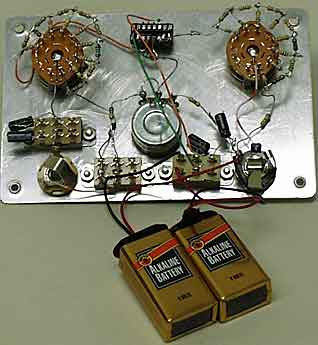
Some component specifics:
5. Setup. Calibration is simple. With SW2 in its 0 dB position and SW3 and SW4 at their 10k Ohm settings, set potentiometer P for zero gain. To do this, load J2 with a 10k Ohm resistor and feed a 1 kHz signal from an audio generator into J1. Adjust P so that the output voltage at J2 equals the input voltage at J1. If no audio generator is available, connect the output of the crystal radio set diode detector to J1 (no audio transformer to be used), and a headphone set of about 10k ohm impedance (2k ohm DC resistance) to J2. Tune in a station and adjust potentiometer P so that the volume is the same as when the detector output feeds the headphones directly. This setting does not have to be changed in the future. Note: Connect the output of the crystal radio set detector to the UITS with as short a length of cable as possible in order to minimize added shunt capacity. If the tone quality of the signal changes from one resistance setting of SW3 to another, the shunt capacity in the detector output circuit is too high. This can be caused by using a diode RF bypass capacitor or an interconnecting cable of too high a shunt capacitance for the resistance setting of SW3 being used. I use an eighteen inch length of RG-59 type coax for my cable. It has a capacitance of about 20 pF per foot. The performance of magnetic diaphragm type headphones can be affected by the DC current passing through them when no coupling transformer is used. SW5 is provided for those who choose to block the DC.
#14 Published: 01/05/01; Last revision: 01/17/10 |