How to measure the impedance of an AM-band antenna-ground system, what one can do with the results, along with some measurementsBy Ben H. Tongue Quick Summary: This Article describes
a method to measure the series capacitive and resistive parameters of
the impedance of an antenna-ground system vs frequency. Results
from measurements on an attic antenna are given.
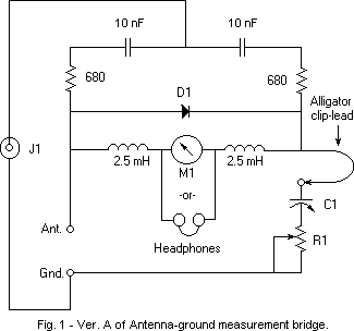
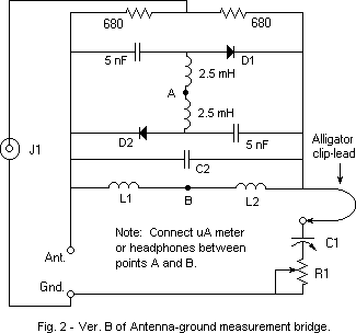
The circuit in Fig. 1 was inspired by an Article in The Crystal Set Society Newsletter of Jan 1, 1995. It was written by Edward Richley. He used a 1 MHz crystal oscillator for his source, so had no problem with using a 200 uA meter. I use a sine wave function generator for my RF source, but a radio Service man's oscillator may also be used if it has enough output. Either of these sources cannot supply as much signal as the xtal oscillator, so I had to increase sensitivity. That's what the 2.5 mH chokes and 5 nF caps are for. The 2.5 mH chokes eliminate RF loading by any resistive component of the meter or phones on the diode detector. The 5 nF caps eliminate resistive DC loading on the detector from the two 680 ohm resistors. I lay out the components breadboard style on a nonconductive table to minimize stray capacity, keep connections short, and especially keep the signal source lead of J1 away from the connections to each end of D1. In my setup D1 is a 1N34A, M1 is a 0-20 uA DC meter, R1 is a 75 ohm non-inductive carbon pot and C1 is a two gang variable cap of 365 pF per section. I parallel the two sections when the antenna capacitance is above 365 pF. A lower sensitivity meter can be used than the one used here, at the cost of a requiring a higher applied signal to J1. If a sensitive enough meter is not available, a pair of high impedance phones (2000 ohms DC resistance) or preferably, a sound powered pair with the elements wired in series can be used. In this case, the generator must have its AM audio modulation turned on at its highest level. A modulation frequency of about 1 kHz is recommended. If the meter is used, do not connect the phones. If phones are used, do not connect a meter. To use the bridge, tune the generator to a frequency of interest. Adjust C1 and R1 for minimum deflection on M1 or a null of the modulation tone in the phones. Increase the RF signal to J1 as much as possible in order to get the sharpest and most precise null. Measure the resistance of R1 with an ohmmeter. Use any desired method to measure C1. I use the cap. measurement range of my Fluke DVM. I'm sure the reader does not need to be reminded that this test involves radiating a weak RF signal from the antenna when making the measurements, so the length of time the generator is on should be kept as short as possible. Possible issues: More sensitivity is needed or interference from antenna pickup of local stations obscures the bridge null. If insufficient signal is available from the RF generator to provide satisfactory meter readings, one can use the more sensitive broadband circuit shown in Fig. 2. The values of L1 and L2 are 2.5 mH and C2 is set to zero in the broadband version. A full wave rectifier is used instead of the half wave one used in Fig.1 and it gives about twice the output. One can also change from using 1N34A diodes and try Schottky Zero Bias detector diodes such as the Agilent HSMS-2850 in either circuit. The HSMS-2855 Zero Bias diode is especially suitable for use in the circuit shown in Fig. 2 since it is a package having two independent diodes, one for D1 and the other for D2. One must be cautious when using the HSMS-2855 because the diodes can be damaged by the application of too strong a signal to J1. This can happen if the signal generator signal is very strong when the bridge is greatly unbalanced. It's best to start with a weak signal, balance the bridge, then increase the signal if necessary. If the signal from the RF generator is not strong enough to override local pickup, thus obscuring the meter null, selectivity may be added to the bridge shown in Fig. 2 by making use of C2 and changing L1 and L2. If L1 and L2 are changed to, say, 10 uH inductors and C2 is made equal to 1200 pF, the bridge will be tuned to about 1 MHz. These changes will reduce the influence of local pickup upon measurement of antenna-ground impedance at 1 MHz. One suitable 10 uH inductor is Mouser's "Fastron" #434-23-100. If one uses headphones instead of a meter as the null indicator, even greater sensitivity can be achieved by AF modulating the bridge signal generator and connecting a parallel L/C tuned to the modulating frequency of the generator across the phones. This will filter out much of the interfering cross talk from local pickup and pass the modulation tone with little loss. Suggested values are L=47 mH and C=0.5 uF if the modulating frequency used is about 1 kHz. A low cost coil having an inductance of 47 mH and a Q of about 9 at 1 kHz is available from Mouser as a Fastron Plugable Shielded coil, #434-02-473J ($1.20 each). Greater selectivity against cross-talk can be obtained by decreasing the inductance and increasing the capacitor. I live about 9 miles from WOR and 12 from WABC, both 50 kW stations. 10 volts peak-to peak applied to the bridge overrides the local radio station pickup sufficiently to provide a clear null on the meter when using the circuit shown in Fig. 1 when using a 1N34A diode. A useable null with an applied signal of only 1.5 volts p-p can be obtained when using the circuit in Fig. 2 with zero bias detector diodes, sound-powered phones instead of a meter and the parallel LC filter. Notes:
What can one do with the measurement results? The main practical thing one can do with the bridge is to Measure and Monitor antenna-ground circuit resistance. This resistance comes primarily from the physical ground, not the antenna and ground connecting leads or radiation resistance of the antenna. Any increase in the antenna-ground resistance serves to reduce the signal power available from the antenna. Any decrease, of course increases it. A halving of the antenna-ground system resistance provides a 3 dB increase in available signal power, if one properly rematches to the crystal radio set input circuit. Measure: One can experiment with different grounds and
various ground paralleling schemes to come up with the one that has
the lowest resistance. Use of this one will result in maximizing
the available signal power (more volume). Experiments using a
counterpoise ground can be made. The other thing one can do, if one is mathematically engineering
a crystal radio set, is to use the R and C values as parameters in the design.
See Article #22. Measurement results on an indoor attic antenna system:
The measured antenna-ground system capacitance was 295 pF at 0.5 MHz, 325 at 1.0 MHz, 410 at 1.5 MHz and and 660 at 2.0 MHz initially. The respective series resistances measured: 17, 12, 10 and 14 ohms. The equivalent reactance elements of this antenna are a capacitance of 285 pF in series with an inductance of 12.5 uH. Since my ground is composed of the house cold water supply pipes in parallel with the the hot water baseboard heating system pipes, much of the capacitance from the horizontal attic antenna wire is to them and the roof, not a real resistive earth ground. That, I think explains the low resistance and high capacitance readings. Probably the ground system is acting as a sort of counterpoise. I decided to see if I could get greater signal pickup by changing to a very crude simulation of a flattop antenna. To do this, I paralleled the antenna wire with a piece of TV twinlead connected to it at each end and at the point of down-lead takeoff. The twinlead was separated from the 7/26 wire by about 2 1/2 feet. The new measured antenna-ground system parameters became: Capacitance: 430 pF at 0.5 MHz, 510 at 1.0 MHz and 860 at 1.5 MHz. The respective series resistance values became: 15, 12 and 11 ohms. The equivalent reactance elements became a capacitance of 405 pF in series with an inductance of 14.2 uH. Signal pickup increased by a negligible 0.8 dB at 710 kHz, and even that was, I'm sure, within experimental error. One may want to compare these equivalent impedance components with the 'Standard Dummy Antenna', as specified in 1938 by the IRE (Institute of Radio Engineers) in 'Standards on Radio Receivers'. My reference for this is Terman's Radio Engineer's Handbook, first edition, 1943, pp 973 and 974. A rather complex equivalent circuit for the antenna is shown on page 974. It is stated that a simpler alternative network, given in footnote #2 on page 973, can be used when only the BC band is of interest. It consists of the series combination of a 200 pF capacitor, 25 ohm resistor and 20 uH inductor. Terman states that the two antenna equivalent circuits have closely the same impedance characteristics in the BC band. The impedance graph on page 974 and the impedance from the series combination of 200 pF, 25 ohm resistor and 20 uH differ, particularly in the resistive curve in the complex equivalent circuit. The 25 ohm resistance in the simplified circuit is probably taken from the resistance in the complex circuit, at the geometric center of the BC band. This resistance is shown as constant in the simplified circuit, and as a strong function of frequency in the more complex circuit. It is suggested that the complex equivalent circuit is theoretically derived, assuming a perfect ground and therefore does not include the resistance of the ground return path. The ground circuit can easily add 15-50 or more ohms to the circuit. #20 Published: 11/24/01; Revised 04/16/2004 © 2001-2008 Ben H. Tongue, All rights
reserved |

