|
Sensitivity and selectivity issues in crystal radio sets including diode problems; measurements of the Q of variable and fixed capacitors, RF loss in slide switches and loss tangent of various dielectrics By Ben H.
Tongue The sensitivity and selectivity in a crystal radio set can be impacted by many factors, including:
A1. There is a practical minimum limit to the possible impedance transformation ratio of the series resistance of the antenna-ground circuit to the shunt value desired across the tank circuit, when the transformation means is just a series capacitor between the antenna and the top of the tank. This problem occurs when the capacitor required for the desired impedance transformation becomes so large that it causes the tank inductance to resonate below the desired frequency (See Article #22, Part 2). The solution here is to use a lower value inductance for the tank or to tap the antenna down on the tank (towards ground). This is why some experimenters find that low inductance tank circuits seem to work better than those of higher inductance. If one does not use a series capacitor for impedance transformation, the antenna may be just tapped down on the tank. Another alternative is to connect the antenna-ground system to a low value unturned inductance that is coupled to the tank. The main advantage of using a series capacitor connected to the top of the tank (for impedance matching) is that it moves the undesired short wave resonance of the antenna-ground circuit (present in every single tuned crystal radio set) to the highest possible frequency and reduces its strength. A disadvantage is that unless a high enough Q variable capacitor is used, insertion power loss is increased, especially at the high frequency end of the band. See Part B, Section 1 of this Article and Article #22, Part 7. A2. Resistive RF losses in the tank circuit are affected by: 1) Losses in any capacitor used for tuning or RF coupling. 2) Physical size of the coil and such items as length/diameter ratio, cross-section size and shape, and turns spacing (to reduce coil proximity losses). 3) Loss tangent in the coil form material, wire insulation and all dielectric material penetrated by the electric field of the coil. 4) Wire size and plating, if any. Silver plating is good but tin plating is bad, especially at the high end of the band. 5) Wire construction such as litz, solid or un-insulated stranded. The latter should be avoided. 6) Switches (if used). 7) Magnetic coupling from the coil to nearby lossy metallic objects. 9) Capacity coupling from "hot" high impedance RF points through a lossy RF return path to ground. See Article #22, point 7 of Part 10. Some comments: The loss from the loss tangent of the dielectric material used for the mounting base of detector stands can be nontrivial. Loss tangent of the material used for a front panel can cause dissipative loss if terminals provided for the connection of an external diode are too close together. See Part B, section 3 of this Article. A3. A diode with too low an axis-crossing resistance (too high a saturation current) will resistively load the tank too heavily, causing a low loaded Q that results in loss of selectivity and sensitivity. A diode with too high an axis-crossing resistance (too low a saturation current) will increase selectivity because it only lightly resistively loads the tank circuit. The disadvantage is that sensitivity is reduced (many people liken this to the diode having too high a "turn-on" voltage.) and considerable audio distortion is generated. A little reverse or forward DC voltage bias will usually fix up these performance problems. See Article #9. A way to check whether weak signal performance would be improved if one used a diode with a different saturation current (Is), but without experimenting with DC bias, is as follows: 1) Give the diode a one second or so spray with an aerosol "component cooler" . The reduction in temperature will temporarily substantially reduce the Is of the diode. If performance improves during the subsequent warm-back-up period, but before reaching room temperature, the diode has too high a room temperature Is. 2) Heat the diode by holding a hot soldering iron next to it for 5 seconds or so or give it a quick blow from a hot hair dryer. If performance improves during the subsequent cool-back-down period, but before reaching room temperature, the diode has too low a room temperature Is. Is, for the usual Schottky diode, changes by about two times for each 10° C. temperature change. Germanium diodes probably act the same. Aerosol component coolers are available from most Electronics Distributors, including Radio Shack. A4. Semiconductor diodes are subject to damage from exposure to electrostatic discharge (ESD) and voltages higher than their reverse breakdown values. Easy-to-check-for damage shows up as an increased reverse current when tested with a reverse DC voltage close to or less than the specified minimum breakdown voltage, as compared to an undamaged diode. Other types of damage can also occur. The effect on detector performance can be anywhere from a mild to a very great reduction of weak-signal sensitivity. This type of damage has the effect of placing a resistor across the diode, which reduces tank Q and adds a parasitic, unneeded audio load resistance. If one has an old VOM having a d'Arsonval moving-coil meter movement (not a digital type) such as the Triplett 360, Weston 980 or Simpson 260, one can do a quick check of the back leakage of a Schottky diode by measuring its back resistance on the X1,000 range. If the needle does not move, the diode has probably not been damaged from ESD. This test does not apply to so-called zero-bias Schottky detector diodes because of their usual low reverse breakdown voltages. Undamaged germanium diodes normally have greater reverse leakage (lower back-resistance) than the usual Schottky detector diodes. This does not effect performance in crystal set applications. The germaniums seem less subject to the electrostatic damage problem precisely because their lower back-resistance (and high reverse breakdown voltages) tends to bleed off any electrostatic charge that might accumulate, maybe from handling. Diodes with the lowest leakage can be selected with a simple test as follows: Connect a 3-4.5 volt DC source, a 4.7k to 10k resistor, the diode and a DVM set to read DC current in series. Polarize the battery so that the diode is back biased. If the current is 2 uA or less, the parasitic back leakage resistance is greater than 2 Megohms or so and all should be well, as far as weak signal loss is concerned. The resistor is used to prevent damage to the test diode if it is accidentally connected in the forward direction. This test may be used to sort out the best weak-signal sensitivity diodes and exclude damaged ones. It is probable that for a selection of diodes having the same part number, ones with the lowest reverse leakage current will deliver the best weak-signal performance. I believe poor weak-signal results some people have reported with the Avago (formerly Agilent) 5082-2835 and HSMS-2820 diodes can be laid at the doorstep of ESD damage. I experienced my first problem with these diodes by storing a few new ones in a propylene vitamin pill bottle for a while. When I wanted a new one I picked up the bottle, shook it (I think,) to see if something was inside and withdrew a diode. It performed badly, so I checked its back resistance with my Triplett 360 VOM as suggested above and found a low back resistance reading. Checking all the others, I found they were all bad. Static electricity did them in... beware! It was pretty stupid of me to not use anti-static bags. BTW, I've never had problems with those diodes if stored in paper bags. The bags must have had enough moisture content to provide sufficient conductivity to bleed off any static charge that might accumulate. It is difficult to properly impedance match these diodes (see Part 4 of Article #5) because of their low saturation current (high axis-crossing resistance). They work best if 3 or or so are connected in parallel to raise the effective saturation current. If one wishes to use only one of these diodes, it could have a low forward bias applied to get the same result (see Article #9). Keep in mind that these diodes do not do very well on strong signals when optimally impedance matched for weak signal reception because of their low reverse voltage breakdown rating. Avago specifies that rating as 15 volts for these diodes. If a rectified voltage approaching 7.5 volts appears across the DC load (now operating in 'peak-detector' mode), a maximum reverse voltage of about 15 volts will appear across the diode for every cycle of the RF carrier. When the diode is operated at this signal level or greater, a 'bucking' rectified current flows through the diode reducing audio output and causing audio distortion. This problem is eliminated by using diodes having a greater reverse breakdown voltage such as most ITT FO 215 and most 1N34A units. A5. A question asked by many
designers is this: What is the best approach when deciding how
to 'impedance match' the transformed antenna-ground-system resistance
to the RF input resistance of the diode detector? This would
be a no-brainer if the resonant resistance of the tank was infinite,
but it is not.
The presence of finite tank loss increases IPL from
the theoretical zero of the matched impedance case. It also reduces
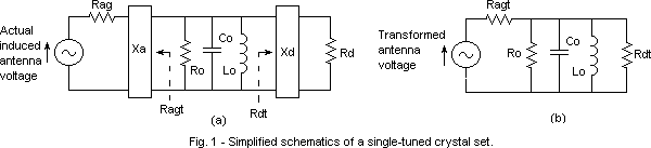
selectivity. Fig. 1a shows a simplified schematic of a single-tuned
crystal radio set. The input impedance transformation Xa might
take the form of capacitor in series with the 'Rag' and the 'induced
voltage source' series combination or a tap on the tank. The
diode input RF resistance transformation might take the form of
a tap on the tank or a capacitor in series with the diode, along
with other components. See Son of Hobbydyne and Hobbydyne
II at http://www.hobbytech.com/crystalradio/crystalradio.htm.
Table 2 shows calculated data for the simplified schematic
shown in Fig.1b.
*Return loss is a measure of the "goodness" of an impedance match. A value of minus infinity indicates a 'perfect impedance match' (all the available input power is delivered to the load). A value of zero indicates a 'perfect impedance mismatch' (all of the available input power is reflected back to the source, and none is delivered to the load). An intermediate value indicates the amount of available power that is reflected back to the source by the load. The usual way of referring to mismatch of a two-port network is by using S parameters. S11 is the input reflection coefficient and S22, the output reflection coefficient. The magnitude of a voltage reflection coefficient is 20*log|{(Rload-Rsource)/(Rload+Rsource)}|. One reference is Radiotron Designer's Handbook, Fourth Edition, pp 891-892. In our case, consider out little circuit (at resonance) to be a zero length transmission line having attenuation. Note that the Handbook was written before 'S" parameters were widely used. Table 1 shows the tradeoff between IPL and selectivity. The lower Rag and Rd become, the lower IPL becomes, but Ql/Qo drops (poorer selectivity). Higher values of Rag and Rd result in greater IPL and greater Ql/Qo (greater selectivity). Ramon Vargas has suggested that many people consider the parameters on line 4 to be close to a practical optimum, and they are. Line 3 shows alternate parameters for achieving the same selectivity at an IPL 0.51 dB less. A general rule may be stated that for any given value of Ql/Qo, equal values for Rag and Rd will result in the least possible IPL. In this case, input and output return losses will be equal. It appears to me that the parameters in lines 3 or 6 are probably the ones to shoot for in most design calculations. An effect I have observed is that one cannot simultaneously attain a perfect impedance match at both input and output ports in systems of the type shown in Fig. 1a (simultaneous conjugate match). As shown on lines 4 and 5 in Table 2, Ragt and Rdt can be arranged to provide a perfect match at one port, but then the other port will be mismatched. Ro could be replaced by a series resistor (not a real-world crystal radio set anymore) and one would still not be able to arrange a simultaneous impedance match. If circuit losses were represented by proper values of both series and shunt resistances, it would then be possible to attain a simultaneous perfect match at both input and output. An audio transformer is one passive device that has series and shunt loss components. If it is so designed, it can provide a simultaneous perfect impedance match at both input and output when loaded by its designed-for load resistances (ignoring reactance effects). If operated at any other impedance level, such as doubling the source and load resistances, simultaneous perfect input and output impedance matching cannot be attained. This info is of mainly theoretical interest for most crystal radio set applications except when one tries to operate an audio transformer at considerably higher or lower source and load resistance values than it was designed for. If this is done, IPL is considerable increased compared to using it the impedances for which it was designed. A6. Audio transformer loss. See Articles #1 and #5. Part B: The Measurements. Loss measurements at various frequencies on some components, with the loss expressed as a parallel resistance (Rp) in parallel with the capacitance of the component or the loss tangent, or equivalent Q of the component:
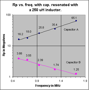
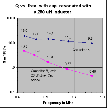
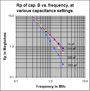
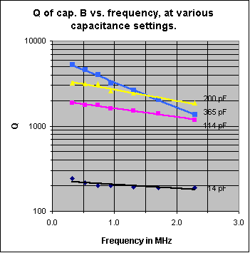
B1: Measurements at 520, 730, 943, 1300 and 1710 kHz, made on two different variable capacitors used in crystal radio sets, are shown in the two graphs below. Capacitor A is a 485 pF variable capacitor that was purchased from Fair Radio Sales. It has a ceramic insulated stator and silver plated brass plates with silver plated wiper contacts. Capacitor B is a small 365 pF air-variable capacitor purchased from the Xtal Set Society. Its plates are made of aluminum and the stator support insulators are made of a phenolic plastic. This capacitor is similar to those sold by Antique Electronic Supply and others. See note at the end of this section B1. Fig. 2 shows Rp plotted against frequency, with the capacitor adjusted at each frequency to a value 20 pf lower than that required to resonate a 250 uH inductor. This allows for a stray capacitance of 20 pF, in an actual circuit. Any losses that may be in the stray capacitance are assumed assigned to the inductor. The plot shows how, in actual practice, the Rp of variable capacitors A and B vary when tuned across the broadcast band. Fig. 3 shows how the Q of the total capacitance (including the 20 pF stray capacitance) varies across the BC band for each capacitor. Do not make the mistake, when looking at the two graphs below, of thinking that they represent Rp and Q of capacitors A or B vs. frequency, with the capacitor set to a fixed capacitance. The capacitance is varied as a function of frequency, along the horizontal axis of the graphs, to a value that would resonate with a 250 uH inductor. Figs. 4 and 5 show Rp and Q of capacitor B as a function of frequency, at four different fixed capacity settings (the frequency at each capacitance setting is always a value that brings about resonance with the 250 uH inductor).
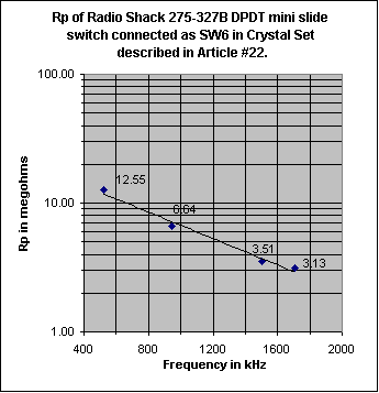
Discussion: There are two main sources of loss in an air-dielectric variable cap: 1) Loss in the dielectric of the stator insulators, and 2) Resistive losses in the metal parts. Of course, there is also the important very low-loss capacitor made from the air dielectric between the plates. The losses in 2) include resistive loss in the plates and in the wiper that connects the rotor to the frame. Resistive loss in the plates is very small at low frequencies, but increases with increasing frequency because of skin effect. Notice, that for capacitor B, Rp (vertical scale) in Fig. 4 is about the same for all capacitance settings at the lowest frequency plotted (310 kHz). Rp is approximately constant over the full 14-365 pF capacitance range. This is because we are varying a high Q air dielectric capacitor of very low loss, in parallel with a low Q fixed capacitance made up of the lossy phenolic stator supports. Most of Rp comes from the loss in the phenolic. In Fig. 5, again at the low frequency end of the horizontal axis, observe that Q is a direct linear function of the overall capacitance, as it should be. The Q of the air-variable part, taken alone, is much higher than that of the capacitor made up of the phenolic insulators. The main loss, here, comes from the approximately fixed shunt Rp provided by the phenolic stator supports. At 14 pF the C from the air cap is relatively low compared to that from the phenolic insulators. At 365 pF the C from the air cap is much higher than that from the phenolic supports. Things change at higher frequencies. The reactance of the capacitor drops. This, combined with the series resistance of the plates and wiper now come into play as an additional factor reducing the Q. If this series resistance (Rs) were the only resistance affecting Q, the equation for Q would be: Q=(reactance of the capacitor)/Rs. One can see from this equation that the introduction of Rs makes the Q drop when frequency increases. Up to now, the main loss came from the parallel loss resistance of the phenolic supports. The Q from a setting of 365 pF drops quite rapidly with increase of frequency because of this series resistance. Skin effect makes the effect worse by increasing Rs, the higher one goes in frequency. Notice that at the low frequency end of Fig. 5, Q is approximately proportional to the capacitance, as it should be if the main loss is the fixed shunt resistance Rp, coming from the phenolic stator insulators. Fig. 5 shows an approximately constant Q (vs. frequency) when the capacitor is set to 14 pF. The loss causing this low, constant Q, comes from the loss tangent of the capacitor formed from the phenolic stator insulators. At low frequencies, Q increases when the capacitor is successively set to 114, 200 or 365 pF because engaging the plates adds a high Q air dielectric capacitor component in parallel with the low Q capacitor formed from the phenolic dielectric supports. As frequency increases, with the capacitor set to 365 pF, one can see that the Q drops at a faster rate than it does when set to 200 or 114 pF. This is because Rs (being in series with the air capacitor, that dominates at the 365 pF setting), acting with its lower capacitive reactance results in a capacitor of lower Q (Q=reactance of air capacitor at 365 pF/Rs). In the Figs. 2 and 3, the capacitor is always set for a circuit capacity value that resonates with 250 uH. This means that at 520 kHz, the varicap is set so the circuit capacity is 375 pF. At 1710 kHz, the circuit capacity is set to 34.7 pF. Even though the capacitor Q goes from 19,000 to 9800 as frequency goes from 520 to 1710 kHz, Rp increases as frequency increases because the circuit capacity must be reduced from 375 to 34.7 pF to tune the tank from 520 to 1710 kHz (Rp=Q/(2*pi*f*C). If the question is posed: 'Is it more important to have ceramic insulated stators or silver plated plates on a variable capacitor used in a BC band crystal radio set?', the answer is that ceramic insulated stators are the way to go. Capacitor A: The main practical conclusion that can be taken from Fig .2 above is that Rp of capacitor A is very high over the whole band and varies roughly proportionally to frequency, over the frequency range of interest: 520-1710 kHz In fact, Rp is so high that it will not contribute any appreciable loss even when used in high performance crystal radio sets using a high Q tank inductor. Another plus is that its Rp increases with increasing frequency, further reducing any effect on loaded Q, sensitivity or selectivity at the high end of the band. The silver plating on the brass plates is beneficial because the resistivity of silver is about 25% of that of brass. Practically speaking, the silver should have little effect on the operation of a crystal radio set in the BC band, but short wave is another matter. The Q of the capacitor drops at higher frequencies, especially when set to a high capacitance value. Silver plating can materially improve performance at higher frequencies by providing a needed higher Q. Be aware that some capacitors are made with cadmium plated brass plates. Silvery-whitish colored cadmium has a resistivity 4.6 times that of silver. This higher resistivity will somewhat reduce Q at high frequencies and at high capacity settings. Some people mistakenly assume, because of the silvery-whitish color, that cadmium plated plates are really silver plated. Capacitor B: One can see from Fig. 2 that Rp of capacitor B varies approximately inversely with frequency. The DLF (dielectric loss factor) of the phenolic stator support insulators is the main cause of this loss, over the whole frequency band. Towards the high end of the band, some loss is contributed by the series resistance in the capacitor plates, the rotor shaft wiper contact and skin effect. This loss effect is greater than that in capacitor A because the resistivity of the aluminum plates is 1.7 times that of silver. Practically speaking, this effect is minimized at the high end of the band because the plates are mostly disengaged. The Rp of the capacitor will have its greatest effect in reducing sensitivity and selectivity at the high frequency end of the band because that is where its value is the the lowest. See note at the end of this Article. The usual crystal radio set uses shunt capacitor tuning with a fixed tank inductance. This configuration causes the tank reactance to be highest at the high end of the band, thus further reducing loaded Q, sensitivity and selectivity, for a given value of Rp. At the low and medium frequency parts of the band, Rp of the capacitor is so high that its effect is small in many crystal radio sets. Highest performance crystal radio sets made with high Q inductors, with careful attention to impedance matching may experience a noticeable reduction in sensitivity and selectivity at the high end of the band when using this or other capacitors using phenolic stator insulation. This is because the Rp of the capacitor becomes comparable to the higher equivalent Rp of the high Q tank inductor at the high end of the band as compared to its value at the low end. To clarify this, an ideal condition would exist if Rp of the capacitor and inductor were infinite. If this were to be the case, and good impedance matching of antenna-ground system to tank, diode to tank and headphones to diode existed, all of the power intercepted by the antenna-ground system would be delivered to the headphones and maximum sensitivity would occur. Any loss present in capacitors, inductors or transformers reduces sensitivity. In this discussion we are dealing primarily with losses in the resonating capacitor and tank inductor, both referred to as their respective values of Rp. The higher the value of these Rps, compared to the transformed antenna-ground source resistance across which they appear, the lesser the loss they cause. One approach to counter the effect the drop in Rp as frequency increases is to change to two-step inductive tuning by dividing the band into two sections as described in Article #22. Technical Note: At any frequency, a real world capacitor of value C1 having a Q of Q1 (Q1>10), can be quite accurately modeled as a series combination of an ideal no-loss capacitor of value C1 and a resistor (Rs) equal to: (reactance of C1)/Q1. Alternatively, at any frequency, a capacitor of value C1, having a Q of Q1 (Q1>10) can be modeled as a parallel combination of an ideal capacitor of value C1 and a resistor (Rp). The resistor, Rp in this case, has a value of:: (reactance of C1)*Q1. Note that since capacitor reactance is a function of frequency, the value of the resistor will, in general, vary with frequency. In crystal radio set design it is sometimes convenient to model the tuning capacitor loss as a parallel resistor, other times as a series resistor. Credit must go to Bill Hebbert for making the time consuming, difficult, precision measurements required for Figs. 2-5. B2: Slide switches used in the Crystal Radio Set described in Article #22 have dielectric losses, as do all switches. To get a handle on this loss, samples of several different types of DPDT switch were measured at 1500 kHz. Each switch except the last three, below, were wired as a SPDT unit by paralleling the two sections. The Q of the capacitance appearing across the open contacts was then measured and Rp was calculated. Rp usually varies approximately inversely with frequency and therefore causes more loss at the high end of the band than at the low end. Contact resistance of all switches was found to be very low. It is unknown how well that characteristic will hold up over time. Note the extremely low loss of the Switchcraft 56206L1. The loss is so low that this switch is overkill in most crystal radio set applications. For applications in which the crystal radio set builder wants to use the lowest loss DPDT slide-switch available, this switch is the best I have found.
Rotary selector switches using ceramic insulation should have very low loss, even lower than the Switchcraft 56206L1. Quality switches using brown phenolic insulation probably have losses similar to slide switches using similar material. I would expect that the slope of the Rp vs. frequency graph of the other slide switches to be the similar that shown above. B3: The loss tangent of an insulating material is the reciprocal of the Q of a capacitor made of that material. Some of the insulating materials listed below are used as front panels, detector stand bases, wire insulation and coil forms in crystal radio sets. A capacitor formed by the use of one of these materials, connected across a high impedance point and ground, will contribute a loss proportional to the loss tangent and capacitance.
Note: GE's version of polycarbonate is called Lexan. A review GE's spec. sheets of various grades of Lexan show loss tangent values at 1.0 MHz ranging between 0.006 and 0.026 . Many grades are specified 0.01. B4: Please see Parts 10 and 11 of Article #26 as well as Table 4. Also see Table 2 of Article #22 and Article #29. B5: Sometimes, when working with high Q tank circuits, a need pops up for a fixed capacitor with a value between say, 100 and 1000 pF that will not degrade overall circuit Q. Generic NPO disc capacitors in that range usually have a Q of around 2000-3000 at 1 MHz. Table 4 shows some caps having higher Q values. The only downside to the high Q caps is that they are SMD types and require some skill when soldering pigtail leads to them to easy connecting to one's circuit. The capacitors were measured singly, in parallel or in series, aiming for values approximating 500 pF. This was for convenience in measurement. I used solid tinned copper wire having a diameter of about 0.010" for my pig-tails. The source for the strands was a piece of stranded hook-up wire.
Note: Solder flux contamination on a dielectric is the enemy of high Q because it usually provides a resistive leakage path. If one gets solder flux on the insulation of a variable cap or switch, remove it with a commercial flux remover. This is important when a DX crystal radio set is involved. |
|||||||||||||||||||||||||||||||||||||||||||||||||||||||||||||||||||||||||||||||||||||||||||||||||||||||||||||||||||||||||||||||||||||||||||||||||||||||||||||||||||||||||||||||||||||||||||||||||||||||||||||||||||||||||||||||||||||||||||||||||||||||||||||
#24 Published: 03/25/2002; Revised: 06/10/2008
0060610