Compare impedance and sensitivity of headphones, and/or speakers even if they differ greatly in impedanceby Ben H. Tongue
The purpose of this article is to show how to compare the sensitivity of two pair of speakers or mono headphones even if they differ greatly in effective impedance. See Article #2 on how to measure impedance. The Dual Fixed Insertion Loss Variable Output Resistance Attenuator (DFILVORA) will be described and directions for its use will be given in Section 1. It is essentially a combination of two FILVORA units along with some extra attenuators. Section 2 will describe how to modify the DFILVORA for use with Hi-Fi stereo headphones. Note: The use of resistors that difer by +/- 10% from the values shown in the schematic should not have an appreciable impact on performance of this unit. Section 1.
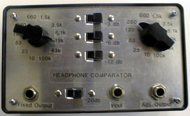
Connect an audio source to jack J3. (I use the output jack of a transistor radio for my source.) Connect the plug of one of the two mono headphone sets or speakers to jack J1 and the other to jack J2. Set attenuators A1, A2, A3, and A4 to 0 dB. Switch S1 should be set to the position providing the loudest sound in the headphone set or speaker connected to J1. Switch S2 should be set to the position providing the loudest sound in the unit connected to J2. (Read Article #2 to see the recommended procedure for doing this.) If the unit connected to J2 is louder than the unit connected to J1, reverse the units. Now add attenuation in the path to the unit connected to J1 in 3 dB steps by using A1, A2 and A3 in the proper combinations (the dB's add), until the volume from the unit connected to J1 equals the volume in the unit connected to J2 as closely as possible. If the sound cannot be reduced to a low enough level because of volume control limitations in the INPUT source, use A4 to reduce the volume by 20 dB.
The sum of the dB settings of A1, A2 and A3 equals the difference in power sensitivity between the two headphones or speakers, independent of the effective impedance of the units. The settings of S1 and S2 indicate the average impedance of the two units. See Article #2 for more details on this subject. The power insertion loss from jack J3 to either jack J1 or jack J2, with the attenuators set to zero, is 29dB. Section 2. To compare the power sensitivity of two stereo headphones, I recommend that several modifications be made to the DIFLVORA. Jack J1 should be changed to a stereo jack and the ring and tip connections tied together. The same change should be made to J2. this will cause each stereo headphone to be tested in mono mode with its elements connected in parallel. The value of all resistors should be halved. The setting of switches S1 and S2 indicate the average impedance over the audio frequency range of two earphone elements in parallel, and that figure will be one-half the value of each element by itself. Also, the measurable range of individual element impedances will be changed from 10 to 100k Ohms to 20 to 200k. The range of impedance measurable for the parallel combo of two elements is still 10 to 100k Ohms. To correct this condition and have the DFILVORA switches S1 and S2 indicate the value of the impedance of one element (and not two in parallel), halve the value of all resistors in the schematic. If this modified DFILVORA is now used to measure a mono headset, the resistance readings of switches S1 and S2 will be twice the actual value. These modifications change the input resistance of the DLVORA to 250 Ohms. #3 Published: 07/15/99; Last revision: 11/04/00 |