Diode Voltage/Current Curves: Does a Specific "Knee" Voltage really Exist?
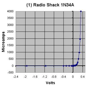
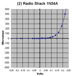
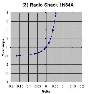
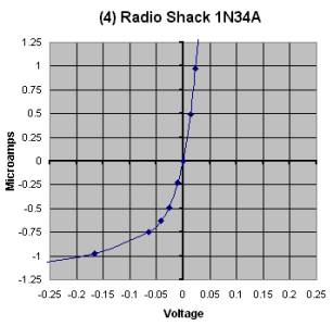
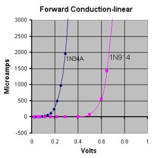
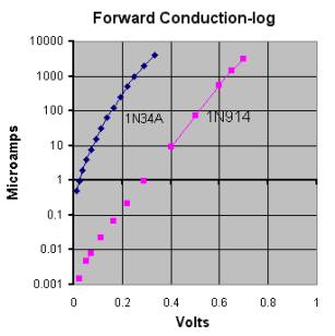
I think that there is validity to the notion of the existence of a diode "knee" when clamping circuits are considered, and maybe with other circuits. I do not think that there is any validity to the notion of a "knee Voltage" in the forward conduction portion of a diode curve when low signal level detection is considered. The reason is that the apparent Voltage of the knee is an artifact of the Current Scale used in plotting the diode V/I curve. In fact, the shapes of the forward conduction curves of all normal diodes are quite similar, and with no "knee", if the Current scale is logarithmic, not linear. To illustrate this, take a look at the charts below. The first four use a linear scale for the Current axis. The full-scale Current values are: 4000 uA, 600uA, 4uA and 1.25uA. The 1N34A diode is one purchased at Radio Shack with measured Is =2.57uA, n=1.6, and Rs=6.55 ohms. The values of Is and n were calculated from measurements made at an effective diode current of 320 uA. The fifth chart shows the 1N34A and a 1N914 using a linear current scale. The sixth chart shows the two diodes using a log Current scale. The 1N914 has n1.85, Is=2.3nA and Rs=6.0 Ohms. Graph #1 seems to show a knee at about 0.2+ Volts. A knee at about 0.2 Volts seems a little ambiguous in graph #2. In graph #3 the knee has vanished. Graph #4 seems to show a knee on the current scale in the reverse bias region! The fifth and sixth graphs show a comparison of the 1N34A and 1N914 in the forward conduction region with a linear and then a log Current scale. Note the apparent knees on the linear plot and the total absence of any knee on the logarithmic plot. For RF diode detectors to work, one needs a device that has a non-linear
V/I curve. In other words, the slope of the V/I curve must change
as a function of applied Voltage. The slope must be steeper (or shallower)
at higher voltages and shallower (or steeper) at lower voltages than at
the quiescent operating point. To clarify this, look at curve #3.
As a low-level signal detector, this diode will rectify if biased at -0.025,
0.0 or +0.025 volts. The difference is that the diode resistance
at the -0.025 Volt operating point is higher than that at 0.0 Volts. It
is lower at +0.025 than at 0.0 Volts. If one places a straightedge
on the screen of one's PC monitor, tangent to the curve at -0.025, 0, and
then +0.025 Volts, one can measure a slope of about 80k Ohms at -0.25 Volts,
40k Ohms at 0.0 Volts, and 20k ohms at +0.25 Volts. The rate-of-change
of slope as a function of voltage (second derivative) is less at -0.025
Volts than at +0.025 Volts. This means that the detection sensitivity when
biased at -0.025 Volts will be less that when biased at +0.025 Volts, even
it the input and output are properly impedance matched.
#7 Published: 01/08/00; Last revision: 05/25/00 |