|
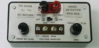
Build the Crystal Set Diode Detector Bias Box: a simple and easy way to determine if one's diode is optimum for weak signal reception, or it should have a higher or lower axis-crossing resistance (0.026*n/Is ohms)By Ben H. Tongue
Quick Summary: The 'Diode Detector Bias Box' enables one to check whether the diode being used in a crystal radio set has optimum characteristics for that set. The optimum detector will deliver the greatest low-signal sensitivity. A detector diode, in order to deliver the highest sensitivity and lowest audio distortion, must be properly impedance matched to its RF source. It must also be matched to the correct (for that diode) audio and DC load resistances. See Articles # 0, 1, 5 and 15a for more info on this subject. How can one know for sure that the diode used in one's own crystal radio set is the best one for it? Another way of putting it is: Does my diode have the Saturation Current (Isopt) that the optimum diode, for my set, would have? An easy way to find the answer is to build and use the diode Detector Bias Box.
To change the detector performance of a diode of Is = Isor (original) to the performance of a diode of Is = Isop (optimum), a DC bias voltage must be inserted in series with the diode. The required bias voltage is: Vbias = 0.0257*n*[ln (Isop/Isor)]. ln represents the natural logarithm of the expression following it. This equation is accurate if the values of Is and n do not change as a function of diode current. This assumption is correct for the Schottky diodes I have checked. Some germanium ones I have checked do not accurately follow the Shockley equation. They tend to have high values of Is such as 500 nA or more. Germaniums having Is values in the 100-200 nA range do seem to follow the Schockley equation well. At high currents, Is increases from its value at low currents. The Vbias equation is given for information only and is not used in the following experimental procedures. Whether a Schottky, germanium or other diode is used, a convenient way to 'tune' the Is of a diode is to use the "Diode Bias Box". It effectively enables one to change a diodes' effective Is (and therefore its operating impedance) by merely turning a knob on a box. The Diode Bias Box also enables one to determine the best diode DC and AC load impedance. Here is an interesting relationship that applies to most Schottky diodes: A Schottky diode detector having a saturation current of (Is1) that has no external DC current bled into it will perform, as a diode detector, identically to that of another diode having a saturation current of (Is2) if a DC current (Ib) equal to (Is1-Is2) is bled into it. To use the Bias Box, connect the terminals labeled T1 to the crystal radio set ground and the cold end of the audio transformer primary, if one is used. If no transformer is used, connect the terminals of T1 to the crystal radio set ground and the cold end of the headphone headset. Also make sure that the connection where the Bias Box is inserted is well bypassed for RF and audio. To operate the box, snap the switch to OFF, disconnect the Hot T1 connection from the crystal radio set and adjust the DIODE DC LOAD pot to the DC load desired (See articles #1 & 4 or pick 100k Ohms to get started). The DC load resistance can be measured across the terminal strip labeled T1 when its hot lead is disconnected from the crystal radio set. Reconnect the Hot T1 connection to the crystal radio set DC return. Tune in the weakest station you can copy. Snap the switch to ON. Adjust the BIAS pot for the the greatest volume. Tune in the strongest station you can get. Adjust the DIODE DC LOAD pot for the least audio distortion. Disconnect the antenna. Connect a DVM to terminal strip T2. If you find a voltage there, that is an indication that your diode is not optimum. A diode having a different Is could work the same, but without the need for any bias. If your diode is biased in the forward direction, the optimum diode would have a higher Is than your present diode. A reverse bias indicates that the optimum diode would have a lower Is. As stated before, the relationship between the required bias (Vbias), the Saturation Current of the original diode (Isor) and the Saturation Current for the optimum diode (Isop) is: Vbias = 0.026*n*ln(Isop/Isor) volts. Some illustrations: To change Is by five times, the bias Voltage required is about 0.044 Volts. To change it by 25 times, the Voltage is about 0.088 Volts. Note: When adjusting the BIAS pot from the optimum position, moving toward forward bias reduces volume, sensitivity and selectivity. Moving toward reverse bias increases selectivity, reduces volume and sensitivity and adds audio distortion. What to do now? If the optimum diode has a higher Is than your present one, several identical diodes can be paralleled to create the equivalent of one of higher Is. For instance, five in parallel will have an Is five times that of one alone. If you have several different diodes, experiment with them. Maybe you can find one that does not need a bias for best results. In recent years many different types of diodes called 1N34A have been sold. Their Is values vary all over the lot. Some final comments: Using the Bias Box to reduce the effective Is of a diode that has a high Is does not work very well if a large reduction is needed. The reason is that diodes of high Is naturally have higher back leakage and a lower reverse breakdown voltage. This causes losses and audio distortion when the RF voltage across the diode swings to reverse polarity every RF cycle. Less sensitivity and selectivity is the result. When one increases the effective Is of a diode that has a low Is by applying a forward voltage bias, this problem does not occur. Some other things that will cause some optimized diodes to work worse than others are: High series resistance (Rs), high diode barrier capacitance (this reduces high frequency performance compared to that at lower frequencies) and high reverse leakage current. #9 Published: 03/30/00; Last revision:01/24/07 |